Day 1 (December 24, 2023)
Deconstructing the Aquila
According to Siboor’s page for the conversion kit, I needed to recycle the frame, PSU, mainboard, bed, Y Endstop and Y Motor.
Disassembling the printer was relatively easy as I wasn’t planning on putting many of the parts back together.
After skimming the manual, I decided I should also tap the extrusions. It was my first time doing this, so it was quite challenging. I printed one of the rear skirts to ensure that the depth was adequate. My Aquila extrusions were tapped on the front, but not the back. I noticed that only the outermost holes were used, so it halved the tapping I needed to do. I did test on some of the inner holes to get the feel of things.
I confirmed that the depth was correct, and continued to printing the rest of the parts.

Day 2 (January 1, 2024)
I am following the Siboor manual.
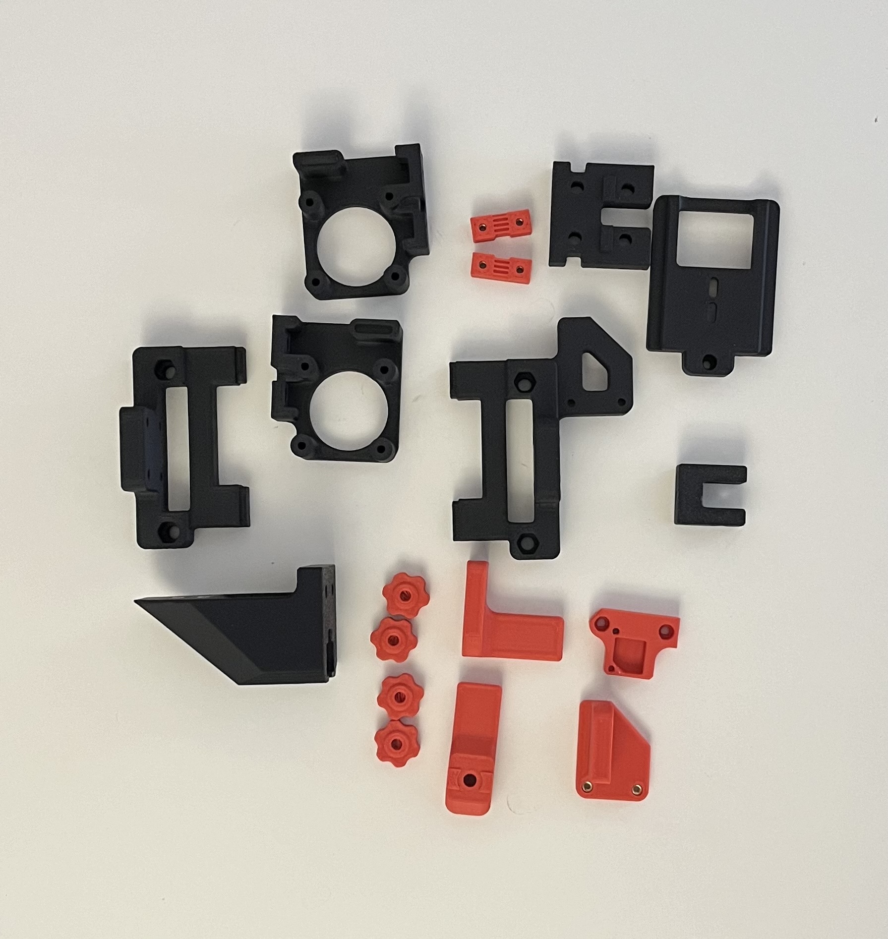
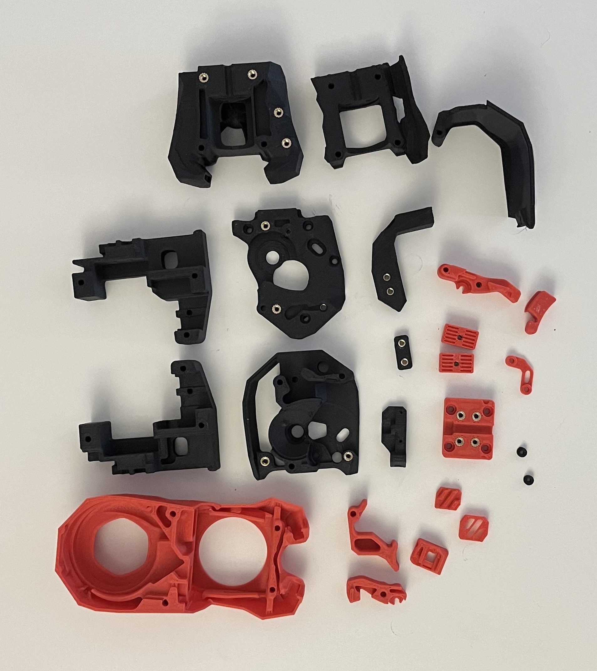
Part Preparation
After printing all the parts that fit on my printer, I had to add heat set inserts.
The parts I wasn’t able to print were:
- skr_mini_e3_mount
- rear_extention_left_a
- rear_extention_left_b
- rear_extention_right_a
- rear_extention_right_b
- grill_front_middle
- grill_rear_middle
- spool_holder_base
- feed_slot
- light_bar_x2
After doing the inserts, I organized the prints into eight bags for assembly.
Electronics

Extensions

Gantry - XZ Axis

Gantry - Y Axis
Grills

Hotend
Misc

Panel Mounting

Frame
Assembling the frame went fairly smoothly. I initially used new bolts from the kit, but reused the old bolts since I wouldn’t have enough.
It wasn’t clear in the manual if I needed to modify the left and right sides. After viewing the CAD, I confirmed I had to do both sides.
Z Rails
I cleaned all my linear rails in isopropyl alcohol and used white lithium grease to lube them. I put the worse rails on my Z axis and the best on the X axis.
I also printed alignment tools for the 2040 and 2020 extrusions.
One thing to note was that the manual no longer mentioned T-nuts.
Y Axis
Installing the Y axis linear rails went smoothly.
I skipped the rest of the Y axis as I wasn’t sure which motor to use.
I intially extracted the Y axis motor from my Aquila, but the pulley was permanently attached. There was a similar issue with the X axis motor. I extracted the extruder motor and moved on.
I assembled the bed assembly, endstop, and idler.
Deviations from the manual:
- For the bed assembly, I used M3x6 FHCS screws instead of the M3x8 SHCS for the cable chain (page 23)
- For the Y endstop, i used M5x10 BHCS to connect the cable chain to the extrusion (page 24)
- For the Y axis idler, I used M5 shims instead of the M3 (page 27)
Skirts
I couldn’t assemble the entire front or rear skirts as I didn’t print the middle pieces. My screws for the display also weren’t catching so I skipped it.
I installed the skirts I did have since I didn’t want the printer to be tilted.
Deviations from the manual:
- For the connecting the skirts, I used M3x10 SHCS instead of the M3x8 SHCS (page 32)
- For the mains inlet, I used M3x10 SHCS instead of the M3x8 SHCS (page 36)
XZ Axis
Similar to before, I skipped the Z and X motor instructions.
I assemled everything else except the belts.
Deviations from the manual:
- For the X extrusion, I used M5x10 BHCS and M3x16 SHCS (page 46)
Toolhead (Stealhburner)
I followed the Stealthburner assembly manual.
I chose the Bi-Metalic head break and CHT nozzle since I plan to print in ABS.
Assembly went well until I installed the cable cover. The toolhead PCB wouldn’t allow for the door to close.
I stopped on page 60 as I didn’t want to complete belting until I did the belts for the Y axis.
Deviations from the manual:
- The Siboor manual didn’t mention the heat set insert (page 11) for the set screw
- The Siboor manual didn’t mention to push some heat set inserts below the surface (page 12)
- Didn’t install LEDs as I didn’t have translucent diffuser (page 47)
Day 2 Photos


Day 3 (January 2, 2024)
Y Axis
Using the extruder motor, I attached the pulley and assembled the parts.
I noticed that when attaching the motor and Y axis idler, the panels didn’t line up with the parts. The Aquila seems to have a slightly different holes compared to the Ender 3 V2. I ended up using 2 more M5 T-nuts and M5x30 BHCS bolts to fix the extrusion so that the parts lined up.
My bed also didn’t align with the mounting holes, so I printed this carriage instead.
The manual also called for 1600mm of belt, but that was way too long. I used a PTFE tube to feed the belt through the extrusion. Due to cutting 1600mm of belt, I was short for the rest of the project.
Feeding the Belt
Deviations from the manual:
- Used two M5 T-nuts and M3x30 BHCS bolts to align Y extrusion (page 14, 26, 28)
- Printed different carraige mount for bed
XZ Axis
When assembling the motor mounts, I ended up running out of M3x30 SHCS screws and ended up using my own. Due to cutting the belt short earlier, I also needed to use extras I had.
I noticed that using the pulley gaps from the manual resulted in the belts being crooked. I also tried the measurements from the official Switchwire manual, but it didn’t solve the issue. I ended up adjusting the pulleys until the belts were straight.
Deviations from the manual:
- The Siboor manual didn’t mention the heat set insert (page 39, 41) for the tensioners
- Pulleys set at different positons (page 39, 41)
Day 3 Photos


Day 4 (January 3, 2024)
Y Axis
With the new carriage, I was able to mount the old bed to the carriage. I had to remove the old strain relief by removing a zip tie and prying off the plastic.
XZ Axis
I removed the belts from the XZ axis and cut them to the same length. I reran them and tensioned them using the tensioners near the motors.
Toolhead (Stealthburner)
I attached the Stealthburner to the X carriage along with the wiring. The vertical cable chain didn’t specify how many links, so I counted from the image and got 20 pieces.
Electronics
I assembled and mounted the Raspberry Pi, power supply, 24V converter, and the Klipper expander board. I couldn’t mount the old motherboard as I didn’t have the mount.
I also ran out of M5 T-nuts and started using the M5 post-install T-nuts. The post-install T-nuts were actually easier to work with since they didn’t slide around.
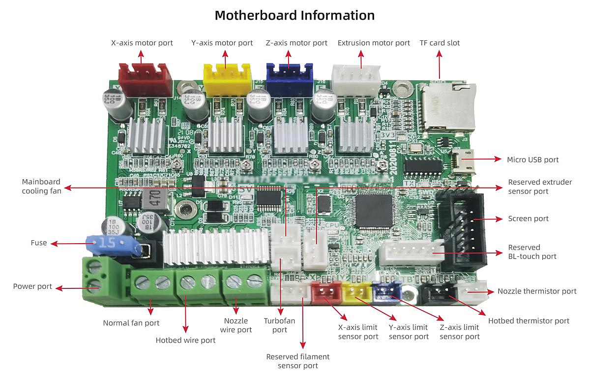
I used the Flashforge motherboard pinout for wiring instead of the manual, as the Aquila was slightly different.
I made my own extrusion cover and mainboard mount.
Deviations from the manual:
- Used M3x16 BHCS with an M3 nut instead of M3x12 SHCS for the screen as they wouldn’t catch (page 33)
- Used custom board mount for mainboard and cover for extrusion (page 72)
- Wires for Raspberry Pi were dupont connectors, used Wagos to add spade connectors (page 77)
- Wires for toolhead (24V) were spade connectors, redid them with ferrules (page 79)
- Used Aquila motherboard wiring instead of Ender 3 motherboard (page 79, 80)
- Used Z end stop wire and motor wire for Y motor since they were shorter (page 80)
- Added finger guard to prevent accidental shocks
- Used cable tie down mount to organize cables
Wiring

Panel Mounting
Mounting the panels went smoothly.
First Power Up
After starting up the printer, I immediately saw a little fire ball. The source was the Klipper expander board. I accidently reversed the polarity, and that seemed to have caused it to ignite.
Klipper Aftermath

Day 5 (January 7, 2024)
Electronics
I rewired my electronics as it was very crammed at the back. I modified the Raspberry Pi mount
Wiring

Flashing Firmware
When I started up the printer, lights turned on and nothing caught on fire this time.
I flashed Mainsail onto an SD card with the Wi-Fi information. After starting up the printer, I was able to update all the software through the Mainsail GUI.
To flash the mainboard, I SSH’d in and ran cd ~/klipper then make menuconfig. I set the config to the following:

After exiting and saving, I ran make. I ran cp ~/klipper/out/klipper.bin ~/printer_data/config/ to copy it to the Config folder and downloaded it via the Mainsail GUI.
I created a folder called Firmware on an SD card and copied the klipper.bin file inside. I did this on a Windows 10 PC just in case.
After inserting the SD card into the mainboard, I turned on the printer and left it for a few minutes to flash.
Day 6 (April 11, 2024)
Software Configuration
I used Ether-3D’s Enderwire 4.2.2 config as the pins seemed very similar to my previous Aquila Klipper config. I made some modifications to my config throughout testing including:
- Including
mainsail.cfgrather thanfluidd.cfg - Changing sensors to
Generic 3950 - Uncommenting
pidfor extruder and heater bed - Changing serial of the mcu
- Uncommenting
z_offset
I decided to do the Klipper screen later.
Initial Startup
Verify Temperature
Both thermistors reported reasonable temperatures.
Verify Heaters
I tested the heaters with a target of 50 Celsius. Only the bed heater heated correctly, the extruder didn’t change. I needed to review the heater_pin
Stepper Motor Check
I used STEPPER_BUZZ STEPPER= to verify stepper_x, stepper_y, stepper_z, and extruder. I noticed that x only moved the left motor and z only moved the right. The y motor moved fine. The extruder motor moved, but there was a grinding sound.
Endstop Check
When I ran QUERY_ENDSTOPS, the X and Y endstops were open while the Z was triggered. I decided to continue with the XY homing and debug the probe later.
XY Homing Check
I verified that the EMERGENCY STOP button worked and began testing.
I ran G28 X and the X axis moved in the right direction. The endstop for the Siboor instructions were on the opposite side of the toolhead, so I had to stop the homing. I changed position_endstop under stepper_x to 0 to fix the homing.
G28 Y homed the bed fine and the endstops worked.