Day 1 (June 27, 2023)
Building the Hardware
I already printed most of the V0.2 parts beforehand as a spare for my original V0.1. I also cleaned my linear rails and applied WD-40 white lithium grease to minimize the mess on the day of.
Since the v1 released a few weeks ago, I’ll likely need to replace or add additional parts.
I followed the V0.2 r1 manual.
Some notable differences I compared to the V0.1:
- I ended up using half the M2 nuts for the rails and faced them towards the rail rather than to the rear. This made installation much easier.
- The Kirigami STLs were updated, but the FormBot kit came with an older version. I ended up printing the V0 nut block, Wago mount, stealth main body, stealth chain mount, and stealth wire guide.
- I needed to print a Z-endstop mount as I didn’t have one.
- I ended up forgetting the two additonal M3 nuts on page 53 as I glossed over the note and ended up installing themlater.
- Printed Swiss Army Jig as it could be differet from V0.1.
- I ended up skipping the feet (Page 101) as the r1 had a new bowden hole and they were taller.
- When installing the leadscrew (Page 108), I ended up dropping all my preloaded nuts.
- I couldn’t get M3x8 BHCS to screw in the motor mount (Page 109) so I ended up using M3x10 BHCS instead.
- After printing the feet (Page 101), I installed the ECSA04 bowden, but not the MR85 bearing or filament runout sensor as the kit didn’t include them.
- I didn’t install any accent pieces as my feet were already red and I had bad experiences with M2x10 screws.


Day 2 (June 28, 2023)
Continuing the Hardware
Notable differences:
- I had to shave some of the motor mount (Page 127) to get the extrusion to sit flush.
- I used three Wagos to wire my bed (Page 148). All the bed wires other than the thermistor went through the Wagos.
- I used the Mini-AfterSherpa and Sherpa Mini for my toolhead (Page 156). My M3x35 screws couldn’t catch onto the x-carriage, so I ended up using M3x40 BHCS. I would’ve used the V0.1 carriage if I did this again.
- I used the V0.1 spacers between the strain relief and motor.
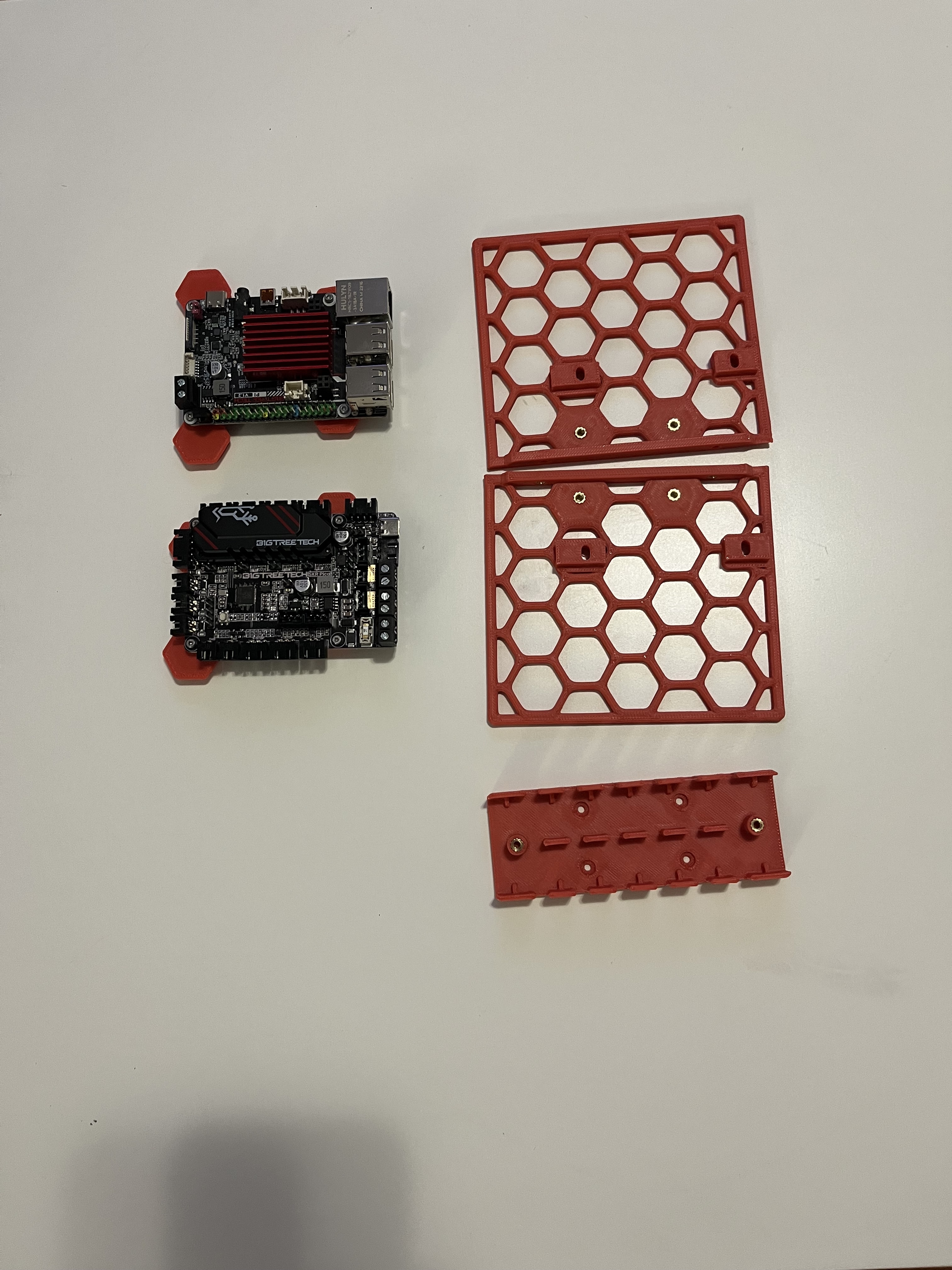
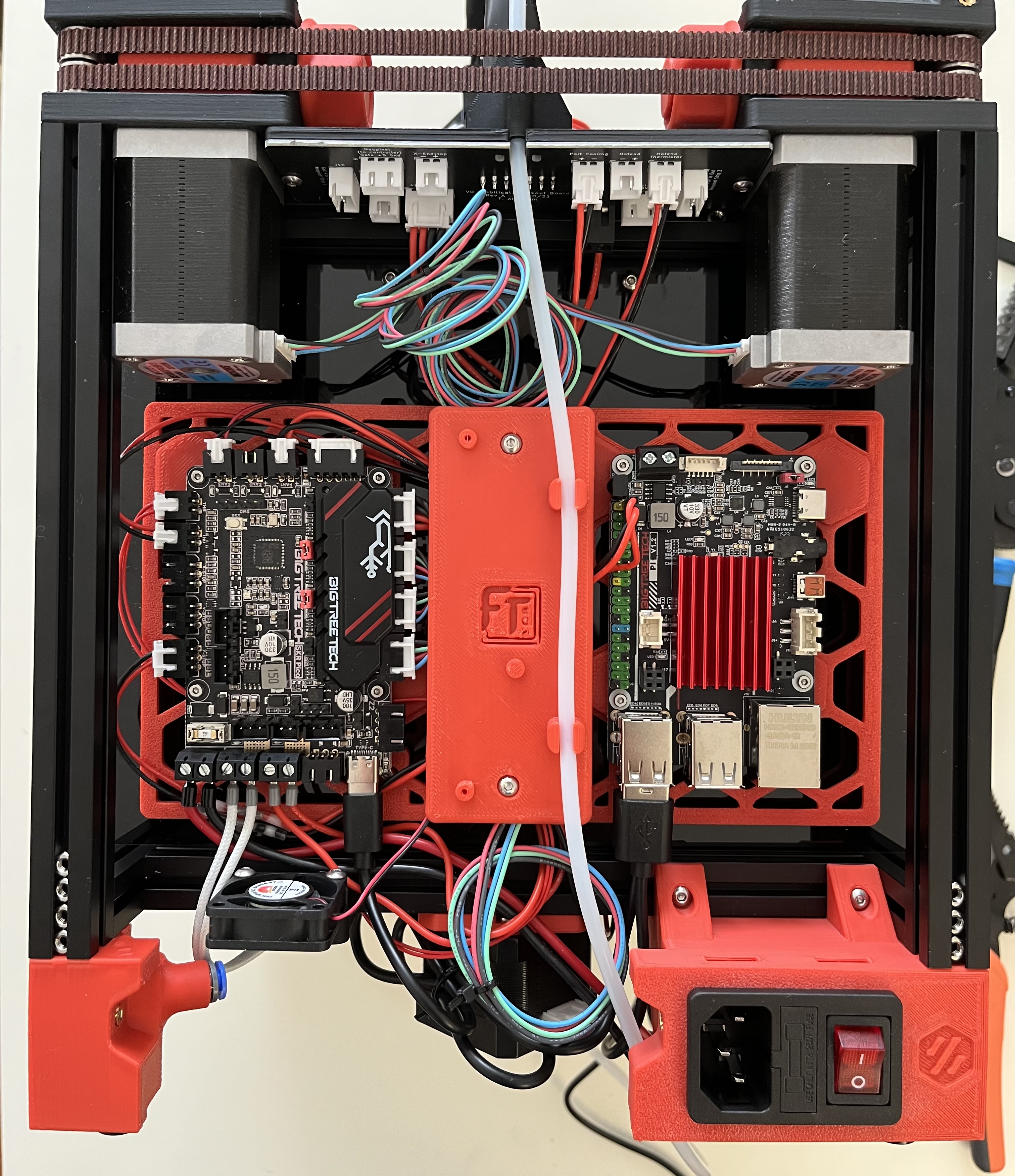
- Instead of the DIN mounts, I opted for Fizzy Tech’s electronics board. Getting the mounts in were a pain, but it was much better than the DIN mounts.


Day 3 (June 29, 2023)
Continuing the Hardware
This day was mostly used to wire everything. I follwed the manual except for the hotend fan as I used a 5V instead of 24V fan. I connected this to the RGB header on the SKR Pico.
The skirts, bottom panel, and some of the top hat were finished. I ended up stopping early as I got an extruder heating eror.

Day 4 (June 30, 2023)
Finishing off the Hardware
I did a PID_CALIBRATE HEATER=extruder TARGET=250 in case there was an issue with calibration. I was able to print the rest of the top hat and panel mounts with some errors. The extruder heating seemed to do fine at first, but gradually got worse. I put this issue off to the side as the parts were finished printing.


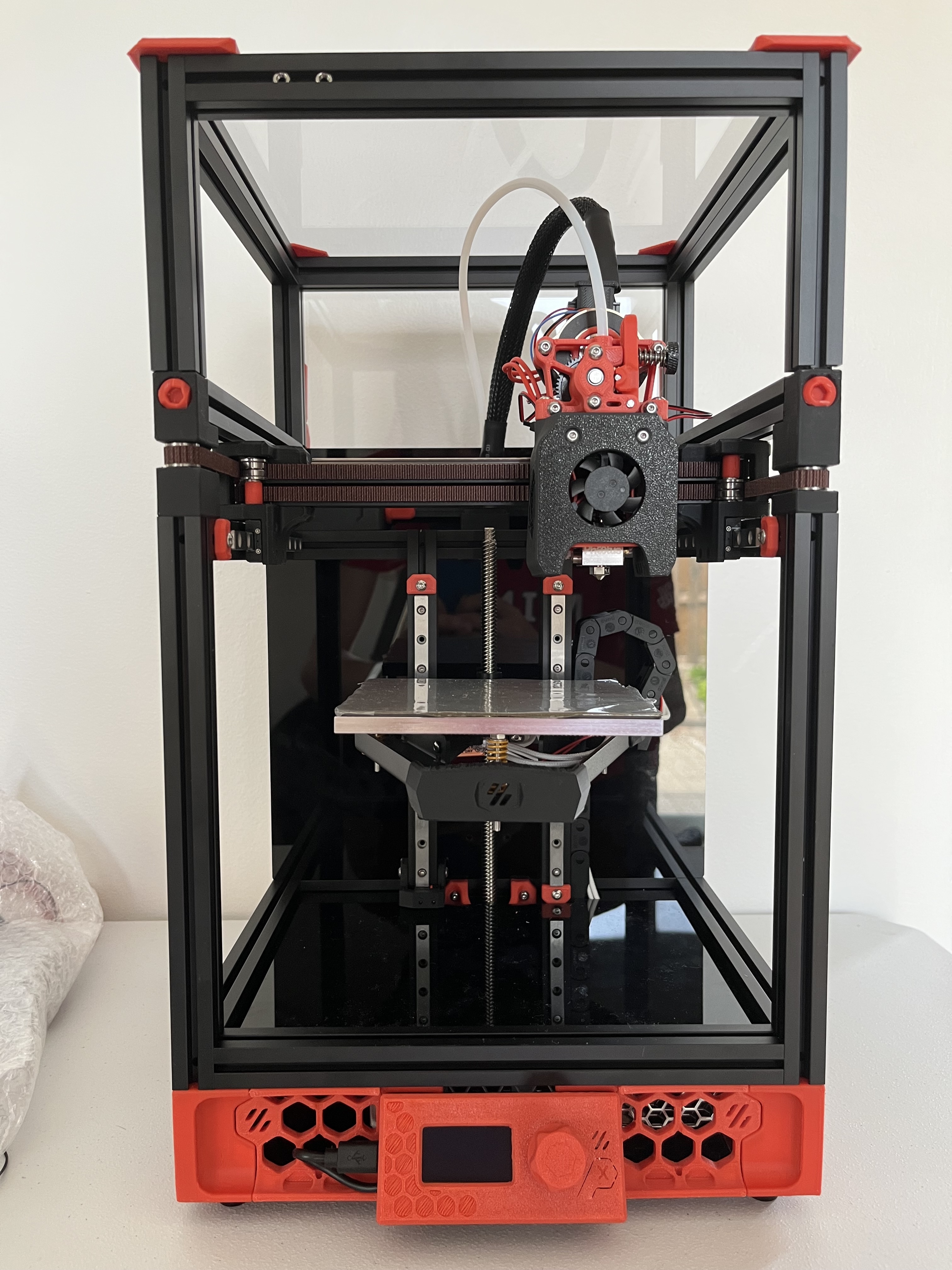
Physically the printer was finished, except for the back panel as I still wanted access to the electronics.

Software
I followed the Voron Mainsail documentation. The BTT Pi didn’t end up showing up on my network, so I looked further into it.
It turned out that the BTT Pi had different flashing instructions. I followed BigTreeTech’s manual for the CB1. I used the latest version from their GitHub which was V2.3.2 CB1_Debian11_Klipper_kernel5.16_20230303.img.xz.
Even after flashing the correct software, I couldn’t get the Pi to connect via wifi. I used ethernet for further configuration.
Flashing Klipper
I created the MCU firmware initially with these settings. I was able to use Mac’s SFTP to download myself a copy.

After I was done, I did poweroff to shutdown the Pi.
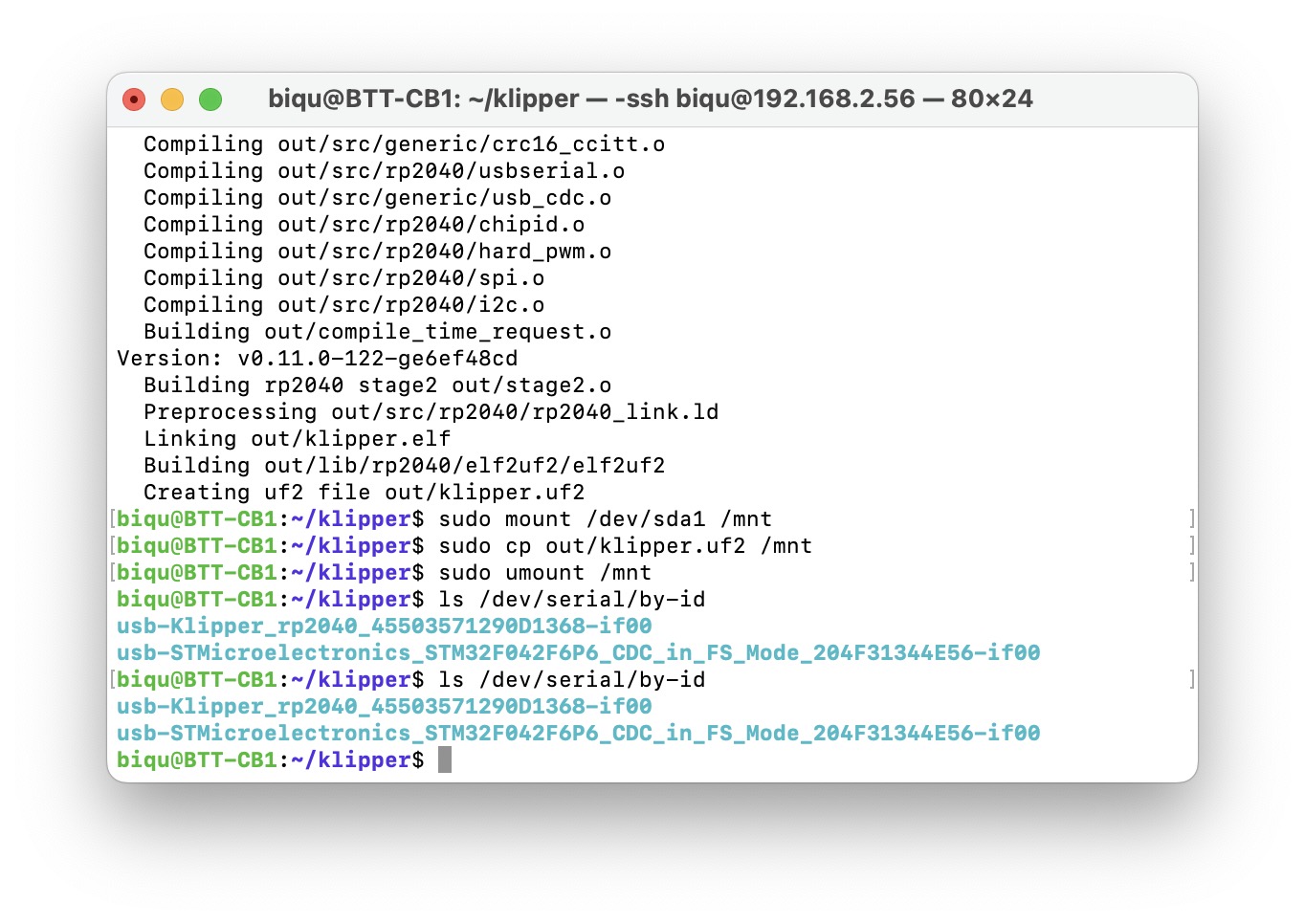
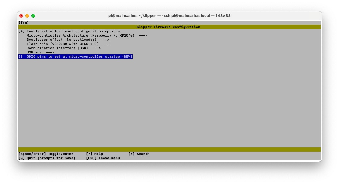
I noticed that the Pico flashing instructions needed a .uf2 file. My current config produced a .bin file so I the firmware with new settings.

cd ~/klipper/
make menuconfig
make clean
make

I used SFTP again to download a copy of the file. For flashing the Pico, I did the following:
sudo mount /dev/sda1 /mnt
sudo cp out/klipper.uf2 /mnt
sudo umount /mnt
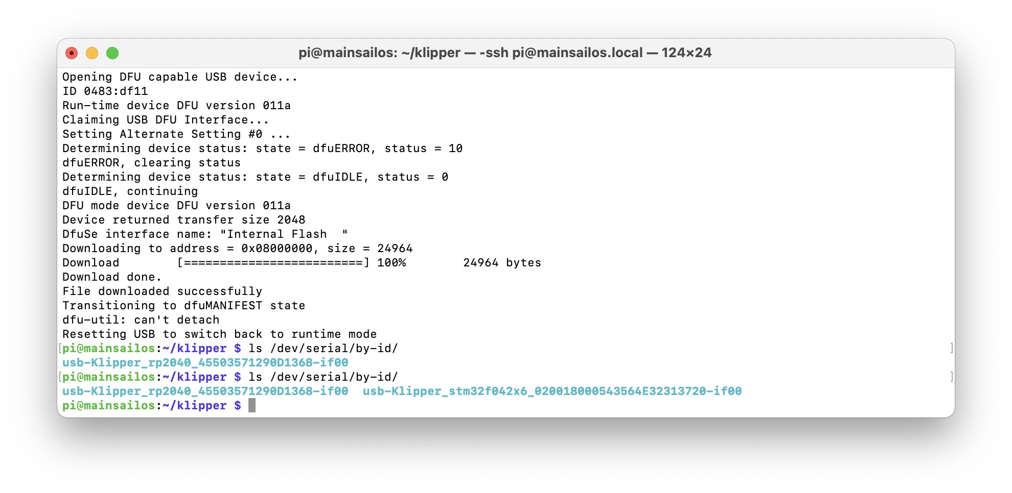
I then removed the boot jumper and hit reset button. After running ls /dev/serial/by-id, I was able to confirm that the Pico was flashed correctly.
Wifi Issues
I tried the following to connect manually, sudo nmcli dev wifi connect "<SSID>" password "<PASSWORD>", but I got the error Error: Connection activation failed: (7) Secrets were required, but not provided..
Following the advice of a forum, I tried nmcli con delete <SSID> and then connecting again. Unfortunately I got the same error.
I found that nmcli dev wifi list also listed the BSSID of a network, so I tried to connect with this command from a forum nmcli d wifi connect <BSSID> password "<PASSWORD>".
I thought of possible issues being:
- SSID name and password
- 2.4GHz and 5GHz band sharing same name
- Router bugs
I decided to put off on this and potentially try my Pi Zero 2W if I couldn’t find a solution.
Day 5 (July 21, 2023)
More Wifi Issues
I bought a micro-HDMI cable to plug directly into the BTT Pi to see if I could access the CLI without connecting it to ethernet. Unfortunately, it seemed that the custom image had a dashboard instead of accessing the CLI. I found ModBot’s video about the CB1, and decided to email BTT to get their suggestions.
Day 6 (July 27, 2023)
Replacement Pi
I didn’t get any response from BTT, so I considered using a Raspberry Pi instead. I had a spare Pi Zero 2 W, so I looked for a USB hub. I found this adapter from SpotPear on AliExpress. There was also a similar model on their website. I opted to get the Pi 4 version since it had USB C power in instead of Micro USB.
While browsing my local listings, I was able to find a Raspberry Pi 3B for under MSRP, so I bought it and installed it instead.
The 3/4 of the mounting holes were the same as the BTT Pi, so I just screwed into the three.
Software
I flashed Mainsail again to my MicroSD card with my Wi-Fi credentials and inserted it into the Pi.
Day 7 (July 28, 2023)
Initial Set Up
I powered up the printer and after a few minutes accessed the WebGUI through http://mainsailos.local/. I was also able to SSH with mainsailos.local.
Once in the GUI, I updated all the packages in the Machine tab.
I already flashed my SKR Pico, so I moved onto software configuration.
I downloaded the SKR Pico configuration and saved it as printer.cfg.
I then uploaded the file ot my Config Files under Machine.
Editing the Config File
I did ls /dev/serial/by-id/ to get my serial. I only got one id, and since it didn’t include “Klipper”, I assumed it was the display.

Reflashing the Pico
I followed the same steps as earlier.
sudo apt install make
cd ~/klipper
make menuconfig
I SSH’d into the Pi and ran the following commands.
make clean
make
I installed the boot jumper and went through the Raspberry Pi method.
I pressed the reset button, then ran the following commands.
sudo mount /dev/sda1 /mnt
sudo cp out/klipper.uf2 /mnt
sudo umount /mnt
After running ls /dev/serial/by-id I was able to verify that the Pico was flashed.

Continuing Config
I used the same thermistor types as my V0.1 since both should have the same hotend.
I calculated the run_currents with this formula.
For the run_current on my X and Y stepper motors, I calculated 0.74 (1.5.707.7). These were MOONS’ MS14HS5P4150-11 motors and rated to run at 1.5A. I saw mentions of 0.9A on the Voron Discord, and might change it later.
My leadscrew motor was a MOONS’ LE174S-T0808-200-0-S-065. The rated current was 0.65A. I calculated 0.32 (0.65.707.7).
My extruder motor was a MOONS’ CSE14HRA1L410A-01. The rated current is 1A, but I people in the Voron Discord recommended 0.7A.
I also uncommented the V0 Display section.
After restarting, Klipper would try to start up, but wouldn’t finish. I commented out the V0 Display section, and it finished starting up. It seemed that I also needed to flash the display.
Flashing the V0 Display
I followed the guide from GitHub. I also referenced 3D-Fab.ZERO’s video.
I plugged in a jumper to the 3.3V BOOT0 pins on the display and started up the printer.
I ran the following commands:
lsusb
cd ~/klipper
make menuconfig

I set the settings to the following: 
I saved and then did make clean and make flash FLASH_DEVICE=xxxx:yyyy with xxxx:yyyy being the STM32 from the lsusb command.
I then removed the boot jumper and pressed reset. I was able to verify that the display flashed with ls /dev/serial/by-id/ and pasted the serial into the config file.
I also set x_offset: 2 and vcomh: 31 to make the display look nicer.
Initial Startup
I set the extruder temperature to 50 and was able to verify that it heated up and that the controller fan worked. I noticed that the hotend fan didn’t spin, and realized I didn’t set the pins in the config.
I set the hotend fan to pin: gpio24 and commented out Neopixel since it had conflicting pins.
I was able to verify that the part fans and bet heater worked.
I verified the motors moved and in the right direction with:
STEPPER_BUZZ STEPPER=stepper_x
STEPPER_BUZZ STEPPER=stepper_y
STEPPER_BUZZ STEPPER=stepper_z
Sensorless Homing
I followed the documentation for sensorless homing.
The V0.2r1 config file already had the endstops configured. I ran SET_TMC_FIELD FIELD=SGTHRS STEPPER=stepper_x VALUE=255 in the console.
I ran G28 X0 and verified the toolhead moved across the x-axis. I kept running SET_TMC_FIELD FIELD=SGTHRS STEPPER=stepper_x VALUE=XXX replacing XXX with lesser values until the x-axis homed. The value for X ended up being 60.
I did the same with Y and it ended up being 50. This was probably since the PTFE tube started pressing against the top hat causing more resistance.
The config already had macros for X and Y.
Continuing Startup
I ran QUERY_ENDSTOPS to verify that the z endstop was open. I then held the endstop and ran QUERY_ENDSTOPS to confirm that it was triggered.
I verified that the small button on the killed the printer. With the button working, I was able to verify that all the axes homed correctly.
I tried centering the hotend, but noticed that when homing X or Y, it would go diagonally a bit. I tried changing the A and B current to 0.9, but it still moved diagonally.
Day 8 (Aug 6, 2023)
Changing Toolheads
The Mini-AfterSherpa mounting could’ve been the problem, so I decided to switch to the default Mini-Stealthburner. While printing the parts on my V0.1, I got another heating issue. It seemed that the thermistor or it’s wires had an issue.
Replacing Thermistor
I had a spare thermistor from an old V6 hotend. It was easy to disassemble the Mini-AfterSherpa and replace the thermistor, along with changing the colour of the toolhead. After reassembling the toolhead, I needed to recalibreate things.
On the first boot up, I verified that the thermistor, heater, fans, and extruder worked. I did M106 S64 and then PID_CALIBRATE HEATER=extruder TARGET=250 to do a PID tune with the part fans at 25%. After it finished, I did SAVE_CONFIG.
I did a BED_SCREWS_ADJUST to adjust the bed screws, and then proceeded onto a test print.
The test print was fine, but I ended up adjusting the bed screws again with it heated to 100 Celsius. I also noticed that my printing profile was extruding at slightly more than 0.4mm, so I fixed it.
Day 9 (Aug 8, 2023)
Temperature Issues
I noticed that even though I replaced the thermistor, I still got large fluctuations. I decided to check the wires and the Umbilical in case there were any breaks. After swapping my Umbilical with the one from the V0.2 kit, the fluctuations disappeared. The wires and connectors looked fine, so I ordered a new kit from AliExpress.
Changing Toolheads
I was able to print the rest of the toolhead fine. The assembly was quite difficult as I had some elephant foot which I needed to deburr. The latch in particular was very snug and hard to close. My tension also seemed to be very light, but I decided to move on.
Day 10 (Aug 21, 2023)
Retesting
I tested the sensorloss homing values again, and ended up with 55 for both the x and y axis. I also changed the pins for the hotend fan to gpio18. I noticed that the hotend fan wasn’t spinning, so I physically swapped the pins, and it worked fine.
The x and y axis still moved diagonally, so I moved onto the next troubleshooting steps.
Troubleshooting XY Movement
I looked through Discord to see if anyone else had this issue. I checked the full_steps_per_rotation, but they should’ve been correct for my motors. I checked my belts and ensured that they were on the bearings.
I decided to open a ticket to see if anyone could spot any issues. They pointed out that the tension on the two belts were different. I tried adjusting the tensioners, but no mattter what, the belts were always different by ~40Hz. I was pretty sure that my belts were the same length, but I decided to redo them just in case.
I confirmed that the belts were indeed the same length, and routed them again. I kept messing around and noticed that even though the tensioners weren’t tightened at all, one of the belts was much more loose than the other. After closer inspection, I noticed that the pulleys were different. The bill of materials had two 20 teeth pullies, but I had one 20 tooth and one 16 tooth. I had ordered additional pullies for a mod, and it seemed that I mixed them up.
After changing out the pully, I reassmbled the printer. The first homing was perfect and there was no more diagonal movement. The Discord really helped a lot as I wouldn’t have noticed the different tensions without them. I ended up using Prusa’s Belt Beta to measure the frequency.
Day 11 (Aug 22, 2023)
Z Endstop Location
I ran Z_ENDSTOP_CALIBRATE to find the position_endstop value. Since I’m running Mainsail, I used the dialog box to adjust the Z until there was a small amount of friction. I then clicked ACCEPT and entered SAVE_CONFIG.
PID Tune
I home all the axes and positioned the nozzle to X:60 and Y:60. I moved the bed to Z:5 and ran PID_CALIBRATE HEATER=heater_bed TARGET=100. Then SAVE_CONFIG once it finished.
I did M106 S64 to set the part cooling fans to 25%, then PID_CALIBRATE HEATER=extruder TARGET=245. Then SAVE_CONFIG once it finished.
Bed Leveling
I ran BED_SCREWS_ADJUST which opened a dialog box and I adjusted the screws until there was small friction with the paper test.
I centred the nozzle again and ran Z_ENDSTOP_CALIBRATE and SAVE_CONFIG once I finished the adjustments.
Extruder Calibration
I heated the hotend to 250 Celsius and tried extruding filament. The extruder was moving in the right direction, but it was not gripping onto the filament much. I was able to push filament myself without any resistance.
I decided to move away from the Mini Stealthburner and found the Sharkfin Extruder. Maverick created a modified MiniSB to work with the extruder. I noticed that the holes seemed to align with the Sherpa Mini, so I went with the Sherpa as I was more familiar with it.
Day 12 (Aug 24, 2023)
Retuning
I redid the sensorless homing as the X hit the side pretty hard and the Y wasn’t working since the Umbilical put too much pressure. I ended up with X:58 and Y:50.
I ran Z_ENDSTOP_CALIBRATE again to redo the offset. I tried loading filament, but the extruder was skipping gears.
Day 13 (Dec 22, 2023)
Toolhead Modifications
The last time I started the printer, the extruder gears were skipping. I switched out the spacers with M3 Female-to-Female brass spacers as the printed ones kept cracking. I ordered the 14mm and 15mm length spacers, but ended up using the 14mm as I preferred slightly too short rather than slightly too long.
Reconfiguring Wifi
I took out the SD card from my Raspberry Pi and inserted it into my Mac.
According to the WiFi-README.txt, I couldn’t change the wifi using the MainsailOS-wpa-supplicant.txt anymore.
I created a wpa_supplicant.conf file with the example file located on the SD card. Since I was accessing the SD card on my Mac, I assumed I was already in the boot partition.
# Simple configuration for a typical WPA2 network

ctrl_interface=DIR=/var/run/wpa_supplicant GROUP=netdev
update_config=1
country=CA

network={
        scan_ssid=1
        ssid="<Name of your wireless LAN>"
        psk="<Password for your wireless LAN>"
        proto=RSN
        key_mgmt=WPA-PSK
        pairwise=CCMP
        auth_alg=OPEN
}
After reinserting the SD card into the Pi, I powered up the printer and was able to access the printer again via http://mainsailos.local/.
Extruder Skipping
I checked the filament path in the toolhead and I was able to manually push filament through each part. I heated up the hotend and tried extruding, but it still struggled. This time, I disassembled the toolhead to see where the filament was getting stuck.
The filament was stuck between the Sherpa Mini and the Sharkfin. I didn’t cut the PTFE tube long enough and it was catching the edge.
I recut the PTFE tube to be slightly longer than needed and kept trimming some until the Sharkfin and Sherpa Mini fit well.
After reassembling the toolhead, I was able to successfully load filament.
I did another BED_SCREWS_ADJUST since I tinkered with the toolhead positioning.
Calibrating Rotation Distance
I calculated my rotation distance following Klipper’s documentation.
- Marked
70mm(ID) from the filament intake. - Extruded
50mm(RD) of filament at 1mm/s via Mainsail - Measured the new distance from the intake,
23mm(SD), actual extrude distance was47mm(70-23) - Calculated new rotation distance: 22.23 * 47 / 50 = 20.8962
After doing this again, it was within the tolerance of 0.5mm.
First Print
I decided to try OrcaSlicer as SuperSlicer hasn’t had a new release since September 2022.
The set up was easy and I selected the V0.1 0.4mm as the printer. I threw in a Voron Cube and sliced it. I set the bed to 100 Celsius and waited 20 minutes until I started the print.

The cube printed well and it was nice being able to access Mainsail from the slicer. The cube was slightly smaller than 30mm, but was quite close. The corners were bulging a bit, so I decided to follow Ellis’ Tuning Guide.


Day 14 (December 23, 2024)
Tuning
I redid my bed screw leveling and Z-offset adjustment with the bed at 105 Celsius and the extruder at 245 Celsius. I did minor adjustments to the Z-offset and saved it once I was satisfied.
This was also when I realized that my V0.1 and V0.2 had different thickness PEI plates.
For Pressure Advance, I used the Pattern Method.
Below are the following settings I set. I tested with the initial PA values, then changed it to test smaller increments. I ended up settling on 0.04. 


The resulting print was much better without bulging in the corners.
Umbilical Issues
Similar to the previous time, the temperature on the extruder began fluctuating until it eventually deviated too much and killed the print. I noticed that my zip-tie kinked the wire quite a bit and that I could actually see some exposed wire.
I debated switching to a CAN bus, but I found a new strain relief for the PTFE tube and one for the toolhead. The creator created one for the AfterSherpa, so I printed that one.