Introduction
One of the concerns I always had with 3D printing were the smell and VOCs. I always printed in a room with a fan exhausting outside, but I wanted to do more. Online people have made enclosures with Lack tables ventilated with HEPA and carbon filters. In the future, I’d like to work on an enclosure, but first I could work with filters.
Since the V0.1 is enclosed, it’s much easier to filter than my Aquila. I found the Nevermore Micro while browsing through Voron mods. There was a smaller version dedicated for the V0.1, so I opted for this solution.
Sourcing Parts
I bought a 24V 2Ball 6000 RPM fan from AliExpress. I had spare heatset inserts, screws, and magnets from building the Voron. I sourced my carbon from Sparta3D. I also considered Jurassic, but the shipping was too expensive.
Printing
I printed the following STLs from the repository.
- FAN_PLENUM_6_3.stl
- FAN_PLENUM_LID_6_3_by_Dom186.stl
- FILTER_CARTRIDGE_6_3.stl
- FILTER_CARTRIDGE_LID_6_3.stl
- BASE_V0_1515.stl
I also planned to redo my cabling, so I printed the following STLs from the V0.2 repository
- PCB_DIN_Clip_x2
- RPi_or_BTT-Pico_Mount
- SKR_E3_V3_Din_Mount
- VHB_Din_Mount_x2
I was able to fit all the parts on my V0.1 bed. I needed to remove skirts and rotate the larger parts 45 degrees.
Planning
In order to fit the additonal cabling, I needed to move around some connectors. I had a chamber thermistor from the Umbilical mod and the fan from the Nevermore.
I read the Reddit post on the nevermore and on the Umbilical.
I decided on placing the chamber thermistor on the SPI1 MOSI and GND pins. I would move the current hotend fan to the Neopixel PA8 and +5V pins. The nevermore fan would use the FAN1 12/24V and PC7 pins.
I used the SKR’s pinout diagram to reference.
Previous wiring

New wiring

Cable Management
I removed the old cable management ducts and mounts for the Raspberry Pi and SKR. I ended up stripping an M2 screw on the Pi and needed to break the plastic to remove the mount. The din mounts installed relatively easy, but the boards rest higher and the SKR keeps popping out due to the pressure.
Assemlbly
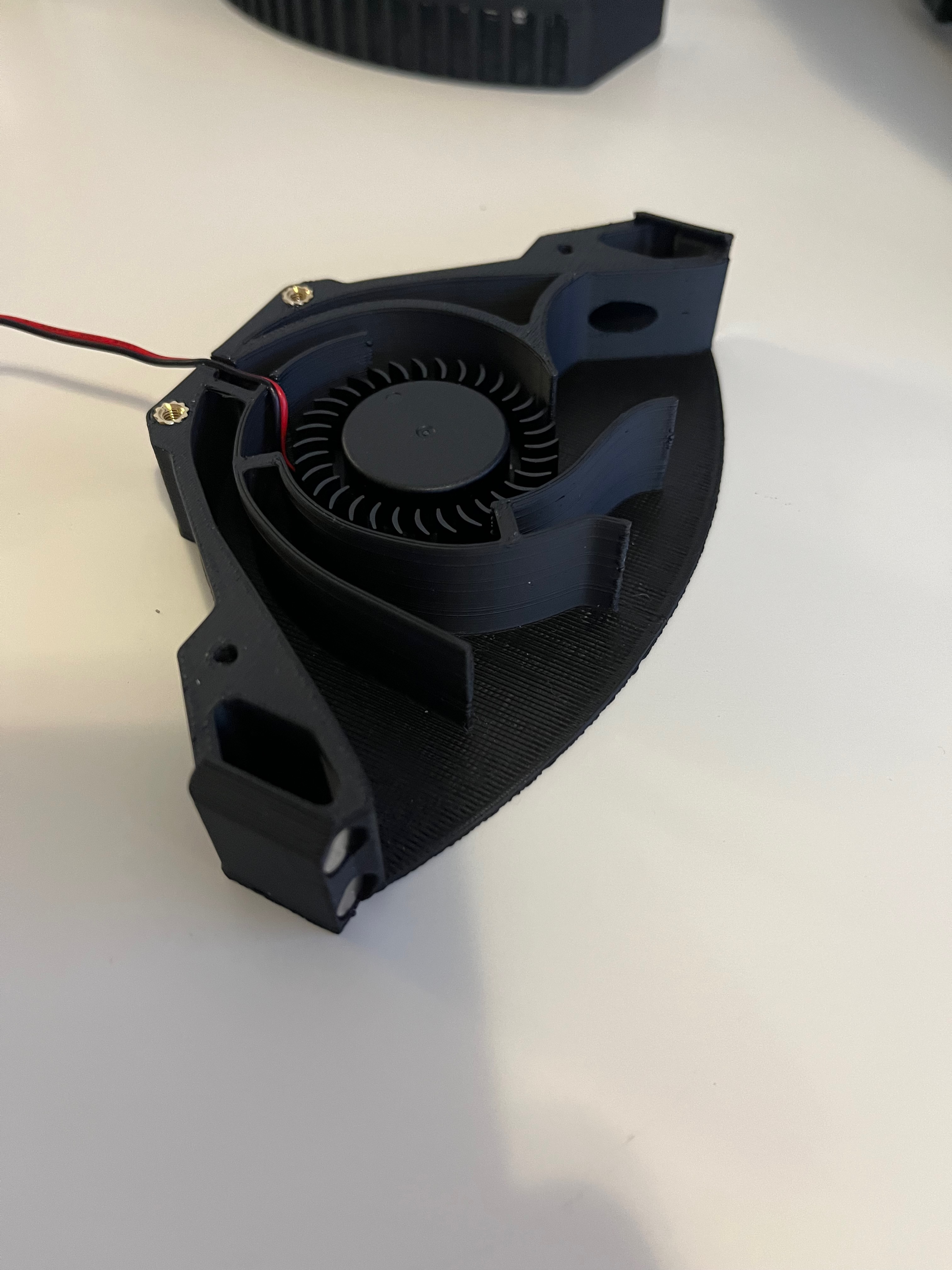
I used super glue to install the 4 magnets. I triple checked the polarities before glueing to ensure that they weren’t reversed as on my V0.1 door handle.

I trimmed the fan shroud and superglued it onto the printed part.
To install the Nevermore, I needed to install four M3 onto the extrusion. I had to remove the front extrusion to install the nuts.

I installed the mount and Nevermore before reinstalling the extrusion to ensure that I had all the necessary hardware.

I routed the cable through the hold for the chain. I ended up extending the cable as it wasn’t long enough. Below is a picture of the wiring.

I ended up mixing up the Raspberry Pi’s GPIO wiring, placing the ground on the 5 volt pin. The cable got very hot and I moved it to the right pin.
Below is a closer up picture of the SKR.

Printer Configuration
I got the code for the thermistor and fans from the Reddit posts above. Below is the code for the chamber thermistor.
#######################################
#### Enclosure Temp Sensor Section ####
#######################################
## Adjust “temerature1:” figure until temps match hotend temps at room temperature.
[thermistor chamber_temp]
temperature1: 64.5
resistance1: 10000
beta: 3950
[temperature_sensor enclosure_temp]
sensor_type: chamber_temp
sensor_pin: PA7 # PA7 is MOSI on the SPI header.
gcode_id: C
Below is the code for the Nevermore fan and hotend.
[heater_fan hotend_fan]
pin: PA8
max_power: 1.0
kick_start_time: 0.5
heater: extruder
heater_temp: 50.0
#fan_speed: 1.0                                                     # You can't PWM the delta fan unless using blue wire

[fan_generic nevermore_fan]
pin: PC7
max_power: 1.0
kick_start_time: 0.5
#fan_speed: 1.0                                                     # You can't PWM the delta fan unless using blue wire
My printer configuration is on my GitHub repository.
After confirming the fans and thermistor worked, I was done.
Conclusion
Overall, this project went much easier than I thought. I left this one last since I thought that the Nevermore would be the most complicated. The hardest part was the wiring as there were so many cables to manage. I’m not sure how I’ll run the Nevermore, but for now I’ll do it manually.
