Table of contents
Introduction
After my experience with my Aquila and the KP3S, I wanted to try something else. One of the better ways to learn is to build a printer from scratch instead of fixing a manufacturer’s mistakes. I wanted to build a Voron v0.1 because it was the cheapest and I was fine with the small build volume. My Aquila would handle the large prints while the Voron would do all the small parts.
Sourcing Parts
The Voron Design website has a configurator that will give you a complete bill of materials and suggestions on where to source the components. I didn’t want to self source the parts as it could end up costing more than a kit with shipping and it seemed like a hassle.
There are several kit options on the market with LDO having the better of the kits. Unfortunately the LDO v0.1 kit costs $899.00+HST. I’d also need to get the printed parts either by printing them myself or via Print it Forward.
I settled on getting a FORMBOT kit after watching 247printing’s video compating the LDO and FORMBOT kit. It also helped that the FORMBOT was $300 CAD cheaper before tax. The kit didn’t come with a Raspberry Pi so I’ll salvage it from my Aquila. The total for the FORMBOT kit was $457.16 USD including shipping and the Dragon Standard Flow hotend. I was also hit with import fees when it arrived.
As for the 3D printed parts, I went with Print it Forward. I’ve never printed with ABS and my Aquila was out of commission as I broke the configuration again. I ended up getting a provider a week after I joined the queue and the parts arrived within 7 days of being assigned. The printed parts ended up costing me $71 USD with the top hat.
Day 1 (June 23)
I read through the manual and went out to buy blue threadlocker and white lithium grease. I soaked my linear rails in alcohol for an hour and moved the carriages around to clean out the shipping oil. I let it dry overnight.
Day 2 (June 24)
I applied the white lithium grease like in NERO 3D’s video and proceeded to start building. I followed the manual from Voron’s website.
I watched the video on doing heat set inserts and used a machinist square to ensure that all my extrusions were straight and at 90 degree angles.
I ended up cutting my belts too short so I needed to purchase more. I skipped forward and did some of the print bed before finishing off for the day. I still needed to do the belts from page 81-86, add a gasket to the bed heater, and solder in the thermal fuse in-line with the heater.
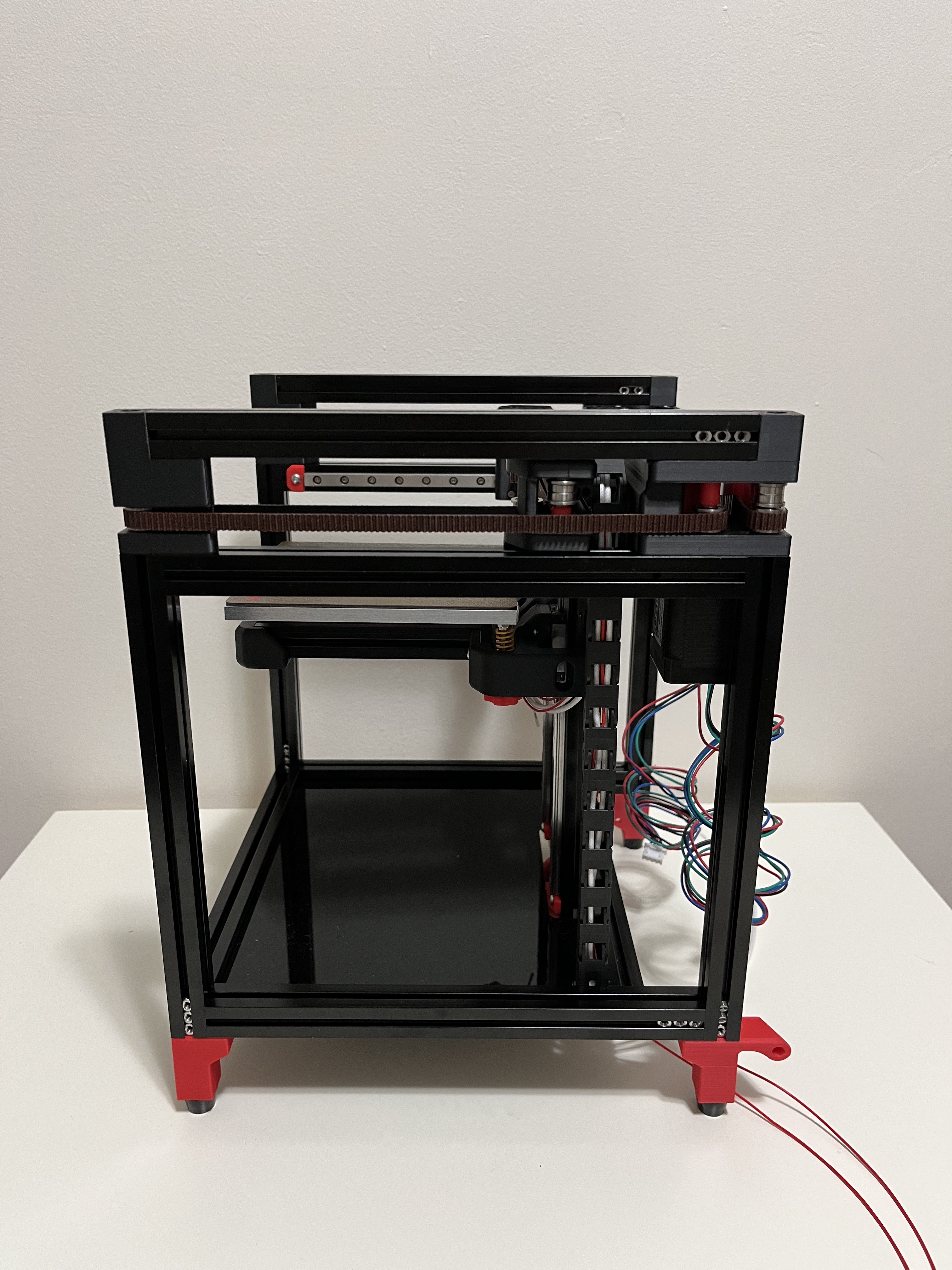
Below are pictures of my progress from Day 2.


Day 3 (July 1)
I applied High-Temp RTV on the sides like in NERO 3D’s V0.1 Build. I then soldered the thermal fuse in-line with the silicone heater with butt connectors. I used the red butt connectors for 22-18 gauge wire.
I zip tied the cables like on page 95 and moved onto the toolhead. Everything went smoothly until page 106. I didn’t know which spacers to do the heat set inserts, so I skipped it for now. I noticed when screwing in my BMG Thumb Screw that my drive gear would start binding. A suggestion from the Voron Discord said to try a shorter spring or longer screw. I used a M3x25 screw in place of the thumb screw and it didn’t bind.
I was then able to continue assembling and mounting the toolhead. I got up until page 122 as I needed the head set inserts from earlier, so I called it a day.
Day 4 (July 2)
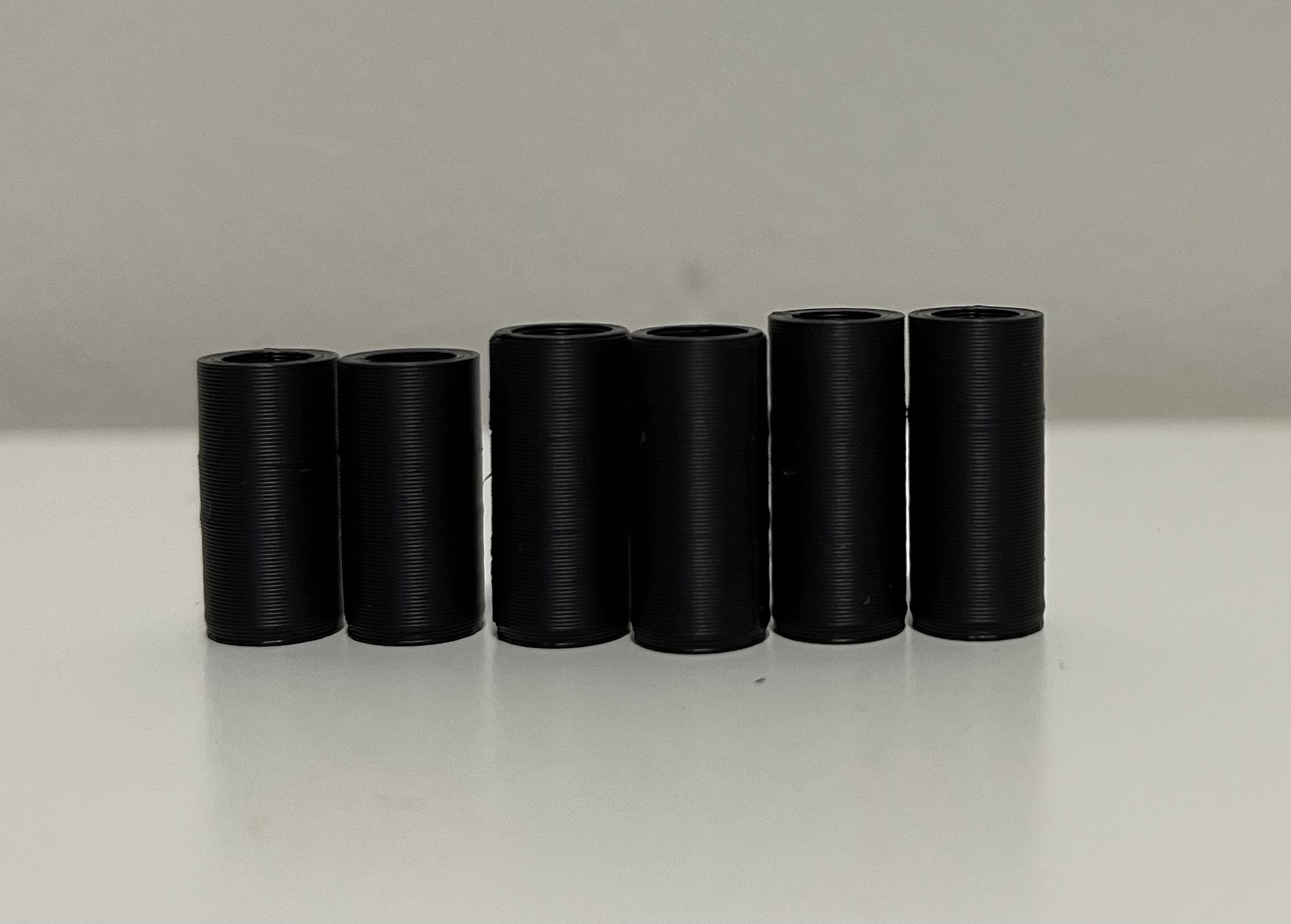
I continued with some of the wiring. I ended up using the shortest spacers in the below picture for the heat inserts as they fit between the motor without being too large.
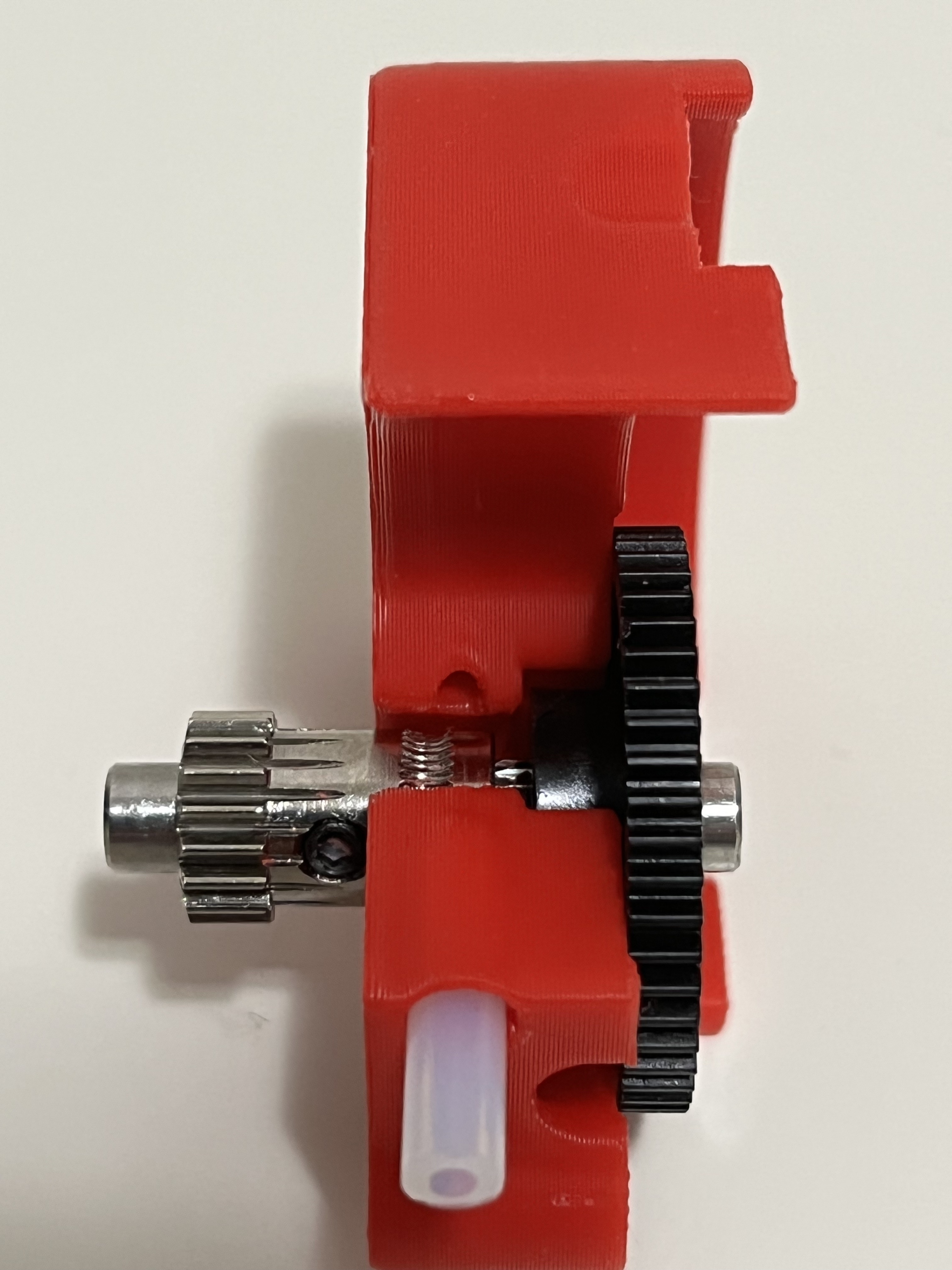
For the toolhead, my teeth were far too left and weren’t aligned with the opening. I ended up hammering the gear into place, but I should’ve been sanding the rod down to make it fit.

I ended up cutting my bed heater wires too short, so I’ll need to rip off the heater and replace it with a new one. I will use wagos in the future.
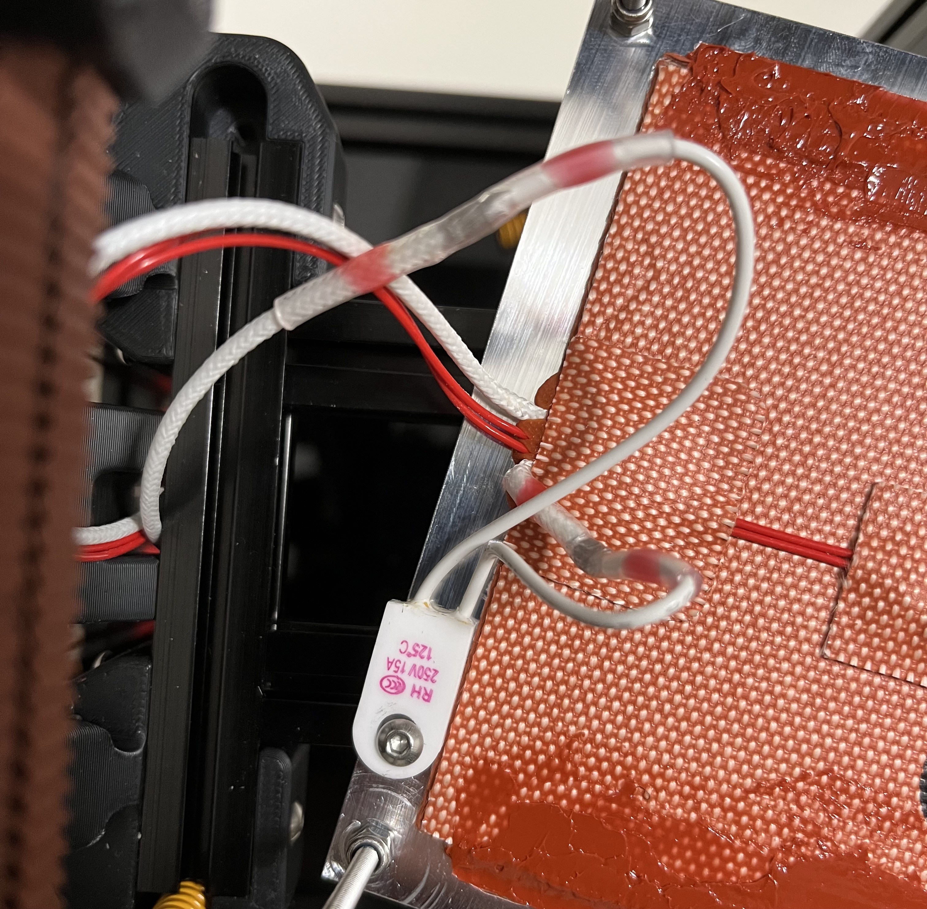
Below are pictures of my progress from Day 3 and 4.


Day 5 (August 5)
My replacement bed heater from keenovo ordered much faster than I anticipated. It took 12 days from the date of the order for it to arrive. I had to wait for a new thermal fuse from AliExpress before I continued.
I continued wiring the rest of the printer. The fork connectors I got from Home Depot ended up being too wide and wouldn’t fit on the power supply terminals.
I had to buy a lot of tools since I didn’t have any. I bought the following tools and parts for wiring:
- IWISS Crimping Tool w/Interchangeable Die Sets for ferrules and fork connectors
- IWISS IWS-2820M for JST connectors
- Wire Ferrules
- 16 AWG Silicone Flexible Wires Black for controller board
- 16 AWG Silicone Flexible Wires Red for controller board
- 24 AWG FEP Flexible Wires Black for extending fan cables
- 24 AWG FEP Flexible Wires Red for extending fan cables
After crimping and routing some more wires, I was able to zip tie the cable loom. I needed to replace the fork connectors and Raspberry Pi to controller board cable as both wouldn’t fit.
Below are pictures of the modified wiring.


Day 6 (August 6)
My right angle cables for connecting from the Raspberry Pi to controller board arrived. It fit much better than the stock cable as it wasn’t strained.
I decided to use the advice of a Discord member and taped the Wagos to my extrusion to guage where I should cut my bed heater wire. It went fine for the fuse until I got to the actual bed wire. I was doing this in the middle of the night, so I forgot that I only needed to cut one of the wires. I ended up needing a third Wago to reconnect the bed heater wires.
I used the zip ties to bundle the cables so they looked less messy and organized. I’m considered commisioning a print of RyanDam’s cable management duct and moving the location of my Raspberry to manage my cables.
Below are the pictues of my progress from Day 6.


Day 7 (August 8)
I got assorted Gardner Bender terminals and used the red #10 spade terminals. The blue terminals ended up being too large and the wire fell out. I was finally able to connect power to the SKR board.
I moved past the wiring and assembled the top hat with great difficulty. Getting the panels to line up and screw in the parts was very hard to do since two panels needed to be held at once. It got better as more screws went in.
I then cable managed the back with zip ties. I decided to use a butt connector to splice the two 24V fans together. I plugged in the power cable to test if anything would blow. Luckily, knock on wood, there was no visible change other than the Raspberry Pi and SKR showing a red LED.
I still need to figure out the jumpers on the SKR, but after that I want to start on the firmware.
Below are the pictures of my progress from Day 7.


